Underground DC cables on land
One technical option open for the construction of new power links as underground cables is to use DC voltage. We are integrating this technology into our transmission grid as part of a pilot application. Crucial to the integration of underground cable for DC links are the laws of physics – especially in relation to capacitance – and our fundamental principle specifying that the new technology must in no way impair the high levels of availability and reliability of our grid. Listed below are the key facts about underground DC cables at a glance:
DC voltage
- The voltage is constant
- Complex converters are required to transform between the various voltage levels (Converter)
- Is primarily suitable for transmitting higher power outputs over long distances from point to point
Underground DC cable
- No reactive power required during operation (one-off charging capacity at switch-on)
- Longer cable routes are possible
- Statutory prioritisation of underground cables for DC links
Capacitance of DC cables
Before a DC cable is able to transmit power, its capacitance must be charged up. Engineers talk of “reactive power”. To achieve this, a DC voltage is applied to the cable.
This procedure can be illustrated by means of a water hose analogy. That said, the inner wall of this water hose is not smooth but is made up of little pockets. If we now pump water into the hose from one end, these pockets are filled up first.

Once all of the pockets are full, the water that is being pumped in at the one end starts to flow out from the other end – and we can use it. The situation is similar with DC cables: once the capacitance of the cable has been charged up, electricity can be transmitted along the cable.

The big advantage of DC voltage is that the voltage remains constant and the capacitance of the cable therefore only has to be charged up once. The “pockets”, then, are “filled with reactive power” only when the current flow is switched on.
As a result, an underground DC cable is able to transmit electricity over hundreds of kilometres.
Experience so far with DC cables
Until now, DC cables have been used primarily for undersea applications. For example, this technology is being used in the North Sea to connect large offshore wind farms located far out to sea with the onshore grid. The industry currently has very little experience with laying DC cables underground on land. To date, they have been used to connect wind power installations out at sea to the transmission grid further inland via what are known as “point-to-point connections”. The industry currently has very few experience with long-distance, cross-country EHV DC cables. Thanks to the new legal framework regulating construction of the corridors using high-voltage direct-current transmission (HVDC), underground DC cables will, however, increasingly be finding their way into the transmission grid in future.
DC transmission: not possible without converters
DC cables require a converter station at both ends of the link – at the starting point and the end point. These convert direct current into alternating current and vice versa.
The converters themselves will be made up of transistors, diodes, capacitors and reactors. To protect these components and the associated control electronics against wind and weather, we will house everything in a hall. Converters of the scale required by an EHV grid are high-tech installations and accordingly very expensive to build. That said, they also offer us some decisive advantages: apart from being able to convert DC voltage to AC and vice versa, we can also use them to stabilise and control the grid voltage.
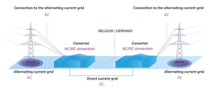
Full-length underground DC link as illustrated by ALEGrO