New technologies
1. STATIC REACTIVE POWER COMPENSATION
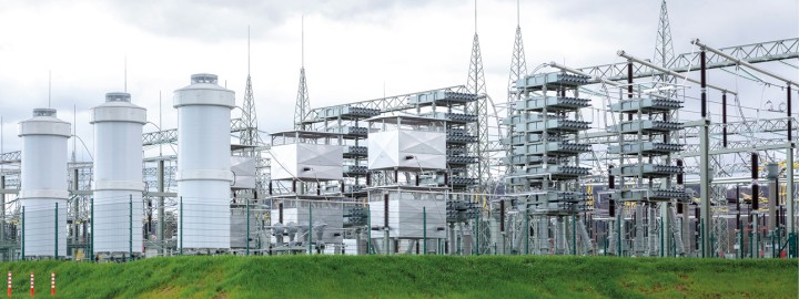
STATIC COMPENSATION DEVICES

Static compensation devices include reactors which are already installed in many Amprion substations. Modern reactors can be regulated in stages and are similar to large transformers. They have a voltage-decreasing effect which is why we always use them in the grid if the voltage in a network node is too high. In the opposite case, i.e. if the voltage is too low, capacitor banks, known as MSCDN (Mechanically Switched Capacitor with Damping Network) systems are used. Compensation devices – both reactors and MSCDN systems – enable us to make better and more efficient use of the supply capacity of our lines for active power transmission. Furthermore they improve the voltage stability and quality of the transmission network.
2. DYNAMIC REACTIVE POWER COMPENSATION
DYNAMIC COMPENSATION DEVICES
In addition, we already use dynamic compensation devices today. They include power electronic compensation devices (static synchronous compensators or STATCOM for short) and rotating phase shifters (RPS). They offer the advantage of a flexible, fast and continuous provision of reactive power and have both a voltage-increasing and voltage-decreasing effect.
STATCOM SYSTEMS
STATCOM systems are made up of power electronic components which can be used to perform dynamic voltage adjustments in the power supply. They also can be used to maintain the voltage level in the grid. They make it possible to adjust the reactive power continuously and in a highly dynamic way, enabling Amprion to react immediately to changing conditions in the grid and stabilise the voltage.
ROTATING PHASE SHIFTERS
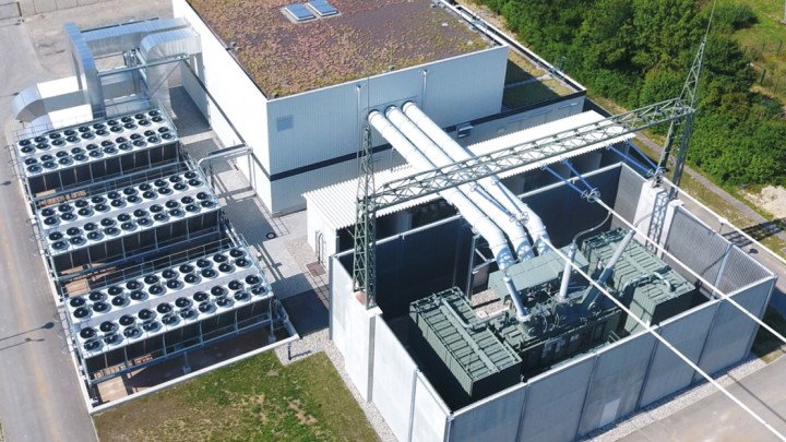
The design of a rotating phase shifter is similar to that of a generator in a conventional power station. However, unlike a power station generator, the rotating phase shifter is not driven by a turbine, but derives its drive power from the electric grid. The synchronous machine used can absorb and generate reactive power and thus contributes to voltage maintenance. In the process, the rotating phase shifter reacts to events in the grid with a similarly high dynamic to the STATCOM system and therefore also contributes to grid stability. However, it takes a few seconds for it to adjust the operating point between the maximum values of voltage-reducing and voltage-increasing operation, so it is slightly less dynamic than the STATCOM system in terms of operating point adjustment.
Additionally, rotating phase shifters offer two advantages: on the one hand, they stabilise the frequency in the transmission network. The mass of the generator, which rotates synchronously with the grid, acts like a flywheel and dampens frequency fluctuations in the grid. This effect can be enhanced by an additional flywheel mass coupled to the generator. On the other hand, due to their physical characteristics, they can make short-circuit power available, which is indispensable for safe grid operations.
3. PHASE-SHIFTING TRANSFORMERS
PHASE-SHIFTING TRANSFORMERS
Phase-shifting transformers are an essential component of the energy transition network. Their role is to ensure a reliable flow of power and to enable more energy to be transmitted in total. The tasks of phase-shifting transformers are different to those of conventional transformers. With their help, grid operators can control the path taken by the electricity. It usually always chooses the path of least resistance and is therefore unevenly distributed. This can lead to problems in the power supply as the lines cannot be loaded in just any old manner. For example, if the volume of transported electricity exceeds a preset value, the overloaded line must be switched off. With the aid of phase-shifting transformers, this overloading can be avoided by deliberately increasing or decreasing the active power of the current (also known as the power flow) on specific lines.
THE PRINCIPLE OF PHASE-SHIFTING TRANSFORMERS
A phase-shifting transformer is controlled according to demand. For example, if the power flow of a line is too high, the control engineers reduce the power flow on this one line by increasing the alternating current resistance. This is referred to as “brake mode”. In brake mode, the line is relieved and instead, parallel lines are loaded more heavily. In what is known as “shift mode”, the control engineers reduce the alternating current resistance, which increases the power flow on the corresponding line.
WHAT IS THE TECHNOLOGY BEHIND ALL THIS?
Unlike conventional transformers used for voltage transformation, on phase-shifting transformers, one winding is connected in series to an electric circuit. A transverse voltage or booster voltage can be applied to the circuit via the other winding. The size and direction of this transverse voltage influence the alternating current resistance and therefore the power flow of the electric circuit. Otherwise, the design and size of the different transformers are virtually identical.
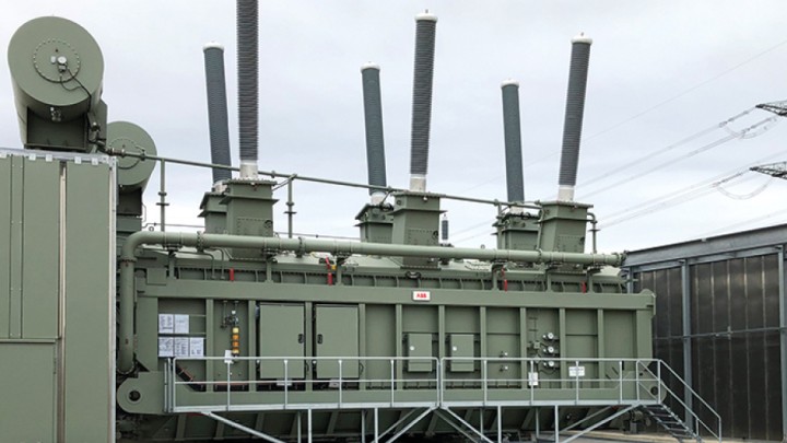
PHASE-SHIFTING TRANSFORMERS: INSTALLATION AND OPERATION
In our transmission network, many lines have two parallel circuits with the same voltage level. As a grid operator, wherever we need to control power flows, we install two phase-shifting transformers – one in each circuit. We take special sound insulation measures when installing phase-shifting transformers by using housing with optimal shielding, for example.