Construction process and recultivation
Properties of Liquid Soil
When excavating a cable trench, the bedding for the protective conduits must be uniformly compacted, sufficiently load-bearing, and free of sharp-edged material. The bedding must also be dimensionally stable over the long term to counteract subsequent settlement or differential settlement and thus prevent undesirable deformation of the cable conduit system. Furthermore, it should not exhibit increased drainage potential relative to the surrounding soil. The liquid soil should also ensure increased thermal conductivity of the soil, thereby helping to prevent potential overheating of the power cable.
Production of Liquid Soil
Since the excavated soil found in the pipeline zone is preferably used and processed on-site for the liquid soil, CO₂ emissions and waste disposal are reduced.
The liquid soil is free of environmentally harmful substances and poses no risk to soil or groundwater. The excavated soil found on-site can be used as the main component for the liquid soil, provided it is suitable. Only in locally limited areas where the excavated soil is not suitable for producing liquid soil are graded sands used instead. Secondary components include layered silicates and cement at ≤ 5% by weight. Water is added to regulate the flowability.
Water Permeability of Liquid Soil
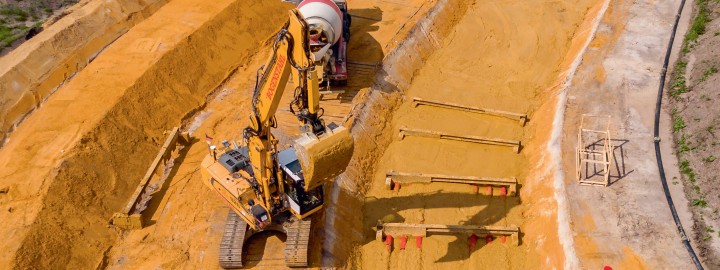
The water permeability of liquid soil is roughly equivalent to that of a silty-cohesive soil. Thanks to its good capillary action, water can also be transported from deeper layers. The liquid soil does not dry out because it has excellent water retention capacity. The liquid soil is transported to the construction site and installed using “truck mixers.” These vehicles resemble concrete mixers but contain liquid soil rather than concrete.
